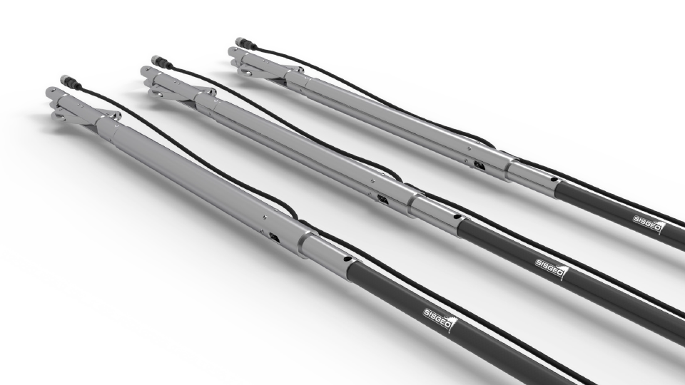
Inclinometri fissi orizzontali

Codici di riferimento: S441 GLI INCLINOMETRI FISSI ORIZZONTALI MEMS SONO COSTITUITI DA UN CORPO IN ACCIAIO DOVE VIENE ALLOGGIATO IL SENSORE E IL CARRELLO A BILANCERE ED UN’ASTA DI PROLUNGA IN FIBRA DI CARBONIO. Le sonde inclinometriche fisse orizzontali vengono installate in catene continue all’interno di un tubo inclinometrico, al fine di monitorare i cedimenti […]
FAQ#116 – How do I configure a WR-Log digital node to read RS485 Sisgeo TIMED sensors?
Sisgeo digital instruments can operate in two powering modes: TIMED or ALWAYS-ON (for more information see F.A.Q.#094).A string of mixed instruments consisting of TIMED gauges and ALWAYS-ON gauges cannot work.The first thing to do is therefore to check that ALL connected instruments in your array are set to TIMED mode.You can check the powering mode […]
FAQ#095 – How long does a chain of digital sensors take to be read?
It mainly depends from the powering mode of the gauges (refer to FAQ#094 for the description of the powering modes). AN EXAMPLE WILL BETTER CLARIFY THE ANSWER. In a batch of 240 gauges, unless otherwise requested by the Customer, the addresses are settled from #001 up to #240. In a borehole is installed a chain of 30 […]
FAQ#087 – Could the IPI, BH Profile and DEX probes have problems in frozen water?
Sisgeo suggest that frozen water within the inclinometer casings is to be avoided due to following reasons: – Ice within the casing will affect functionality of the systems by blocking the individual probes;– Mechanical damages can occur to the probes, but also to the inclinometer casing due to the expansion of frozen water In any […]
FAQ#076 – Perchè è necessario aggiungere una resistenza di terminazione sull’ultimo sensore digitalizzato di ogni catena RS-485?
Tutti i sensori digitalizzati SISGEO (IPI, Tilmetri, H-Level, RDS ) usano il protocollo di comunicazione seriale RS-485. Il protocollo RS-485 contempla una resistenza di terminazione. Il collegamento raccomandato per una catena è il “punto-punto” (multidropped) in modalità bus (linea). Collegamenti a “stella”, ad“anello” o multipli non sono raccomandati. I datalogger SISGEO sono già predisposti con […]
FAQ#075 – What parameters are saved in SISGEO digital sensors? What information must the Customer provide when ordering?
All SISGEO digital sensors (e.g. IPI, BH Profile, MD Profile, LT Inclibus, Tilt-meter, RDS, H-Level, etc.) use the Modbus communication protocol over RS-485 serial. SISGEO digital sensors are connected to each other with a single signal cable. The parameters that are configured at the factory for each digital sensor are as follows: Upon confirmation of […]
FAQ#074 – Che tipo di acquisitore è necessario per leggere i sensori digitalizzati SISGEO?
Per leggere i sensori digitalizzati SISGEO è necessario utilizzare un datalogger Modbus Master (es. OMNIAlog e miniOMNIAlog). I sensori sono letti mediante il cavo connesso ad un interfaccia RS-485 (DCE, Half-Duplex, no Echo) in grado di gestire il protocollo Modbus RTU SISGEO. La documentazione del protocollo Modbus SISGEO vi è disponibile sul sito SISGEO. E’ […]
FAQ#073 – Qual è il numero massimo di sensori digitalizzati (RS-485, modbus), il numero massimo di catene e la distanza massima del cavo di collegamento in una rete RS-485?
Ultimo aggiornamento: ottobre 2021 Tutti i sensori digitalizzati SISGEO utilizzano il una interfaccia RS485 con protocollo Modbus. 1. Il numero massimo di sensori digitalizzati in una rete RS-485 è 247 (teorico). 2. Il numero massimo di catene di sensori digitalizzati collegabili ad un Modbus master (OMNIAlog e miniOMNIAlog) è 4. 3. Per le distanze massime […]


