



Explore Eddyfi Technologies Product Lines ▼

Accessoires de test pour vérin plat

Codes de référence: L100

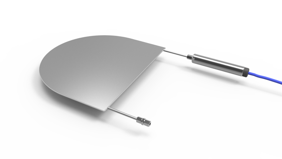
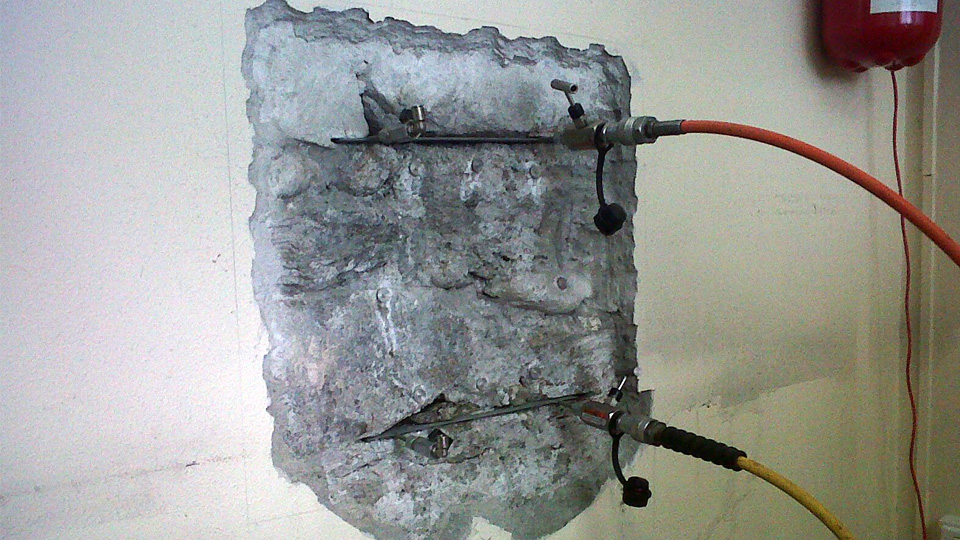
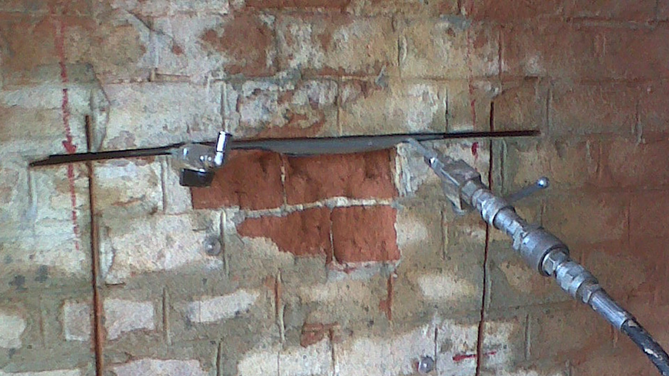
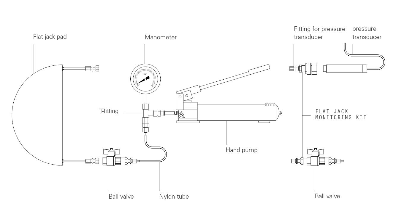
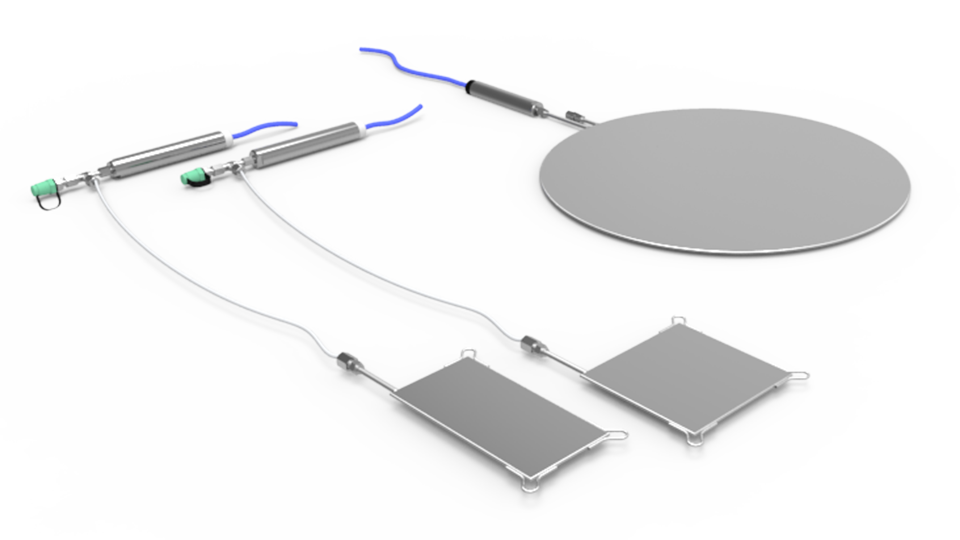
Le vérin plat se compose d’une cellule de pression en acier, remplie d’huile désaérée et équipée de deux conduites en acier, l’une pour la connexion à une pompe et l’autre pour connecter un capteur de pression ou un autre vérin.

Les cellules sont disponibles en différentes dimensions; des formes et dimensions variées sont réalisables sur demande.

La pompe manuelle est fournie avec un manomètre qui permet de surveiller la pression d’huile du vérin pendant le test.

Un kit de surveillance automatique spécial est disponible afin de connecter un capteur de pression au vérin plat: cette solution permet la connexion du vérin plat à un enregistreur de données pour l’acquisition de données et l’envoi d’alertes automatiques.

Resistive pressure transducer sensor is a spin off from thick film technology using the piezo-resistive characteristic of specific resistive inks. Resistors, formed using screen printing techniques, are deposited on a deformable ceramic diaphragm substrate to form strain gauge arrays. Strain changes from external loads applied to the deformable ceramic diaphragm result in resistance changes of the strain gauge arrays.
The electric signal from the strain gauge arrays is directly proportional to the stress applied to the diaphragm. Sensor is constructed of a ceramic, analogous to a crystal structure, to form a pressure diaphragm chemically inert with near perfect mechanical characteristics. Screen printed resistors are deposited onto the diaphragm to form a 4 arms Wheatstone bridge.
A fixed excitation voltage is applied to one diagonal of the circuit. Strains experienced by the diaphragm will change the values of the individual resistors within the Wheatstone bridge resulting in a bridge unbalance. This unbalance produce an output signal from the other diagonal of the Wheatstone bridge, directly proportional to the applied stress.
An electronic board converts this signal into 4-20 mA suitable for transmission over long distances to remote readouts or to data acquisition systems.

Vibrating wire transducer is essentially composed by a taut wire clamped at its ends and tensioned so that it is free to vibrate at its natural frequency. The frequency of vibration varies with the wire tension and thus small relative movements between the two end clamps.
With vibrating wire transducers frequencies rather than voltage levels are measured, so a dedicated readout/datalogger must be used to measure the resonant frequency. These ones excites the vibrating wire transducer, measures the response, performs some calculations on the response, and returns the result.
SISGEO vibrating wire transducer uses ‘pluck and read’ method and not ‘auto resonant’ method; when the readout/datalogger plucks the wire a magnetic attraction is created to the coil and the wire start to vibrate and it causes an alternating voltage of the same frequency of the natural frequency of the wire; the voltage signal is transmitted on the cable and read from the readout/datalogger.
Vibrating wire transducers have a reputation for long expected life and long-term stability.

Lisible par

Fiche technique

Manuel

Faq connexes

Produits connexes

Explore Eddyfi Technologies product lines

Automated Vision System Icon Automated Vision Systems
ET/UT Solutions Icon ET & UT Solutions
Nuclear Steam Generator Icon Nuclear Steam Generators
Remote Monitoring Solutions Icon Remote Monitoring Solutions
Robotics Solutions Icon Robotics Solutions

Fundamentals of digital instrumentation:

Key concepts for reliable sensor-to-datalogger communication

Date: 25/06/2026
Time: 17:00 GMT+1
Duration: 60 minutes
Speaker: Eng. Nicola Aresi
Language: English

Find out more: SISGEO FREE WEBINAR – Fundamentals of digital instrumentation

Sisgeo Piezometers: Comprehensive Solutions for Groundwater Monitoring

What You’ll Learn:

  • Detailed overview of Sisgeo’s range of piezometer technologies including vibrating wire and electric piezometers, outlining their operating principles, installation methods, and suitability for diverse site conditions.
  • Selection of piezometer filters, emphasizing materials and designs that conform to ISO 18674-4 standards.
  • Integration of piezometer data with automated acquisition systems.
  • Best practices for calibration and maintenance standards.

When:Thu, Jul 31, 2025 3:00 PM – 4:00 PM CEST
Language: English

Sisgeo presents the new MD-Profile IPI with 360° calibration
Discover the next generation of In-Place Inclinometers for geotechnical monitoring!

The new MD-Profile 360° features:

  • new removable pressors available for 3 different tube ID
  • new triaxial calibration over the entire 360° range
  • even stronger connectors

When: 27/05/2025 3:00 PM – 3:30 PM GMT+1
Language
: English