Fuel terminal monitoring

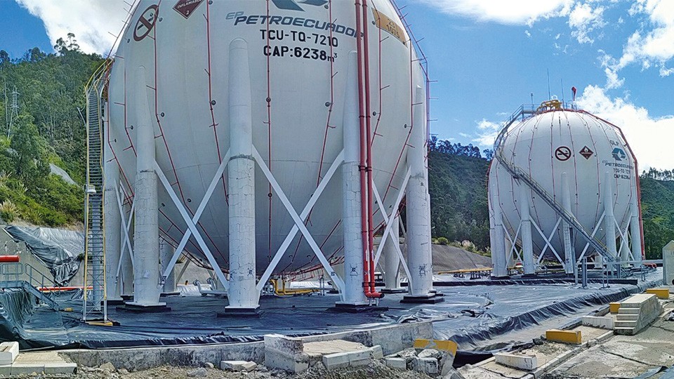
Suministro de instrumentación para el monitoreo de tanques del terminal de combustible en la ciudad de Cuenca, Ecuador. El alcance incluye monitoreo de asentamiento de las estructuras a través de celdas de asentamiento H-Level y clinómetros. En terreno, los asentamientos y movimientos horizontales del terreno se evaluarás a través de sondas inclinométrica IPI y sondas […]
Sensores Tilt Beam (TB)

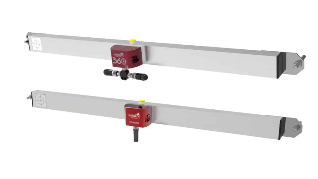
Códigos de referencia de los productos: S700, S7BM Tilt Beam (TB) sensors can be used both in chain to measure a continuous displacement or in stand alone application to measure the tilt-displacement between two point (ends of the beam). As all Sisgeo’s MEMS tilt sensor, they use the latest MEMS technology that grant great performance and […]
Rome Underground – Line C – Italy

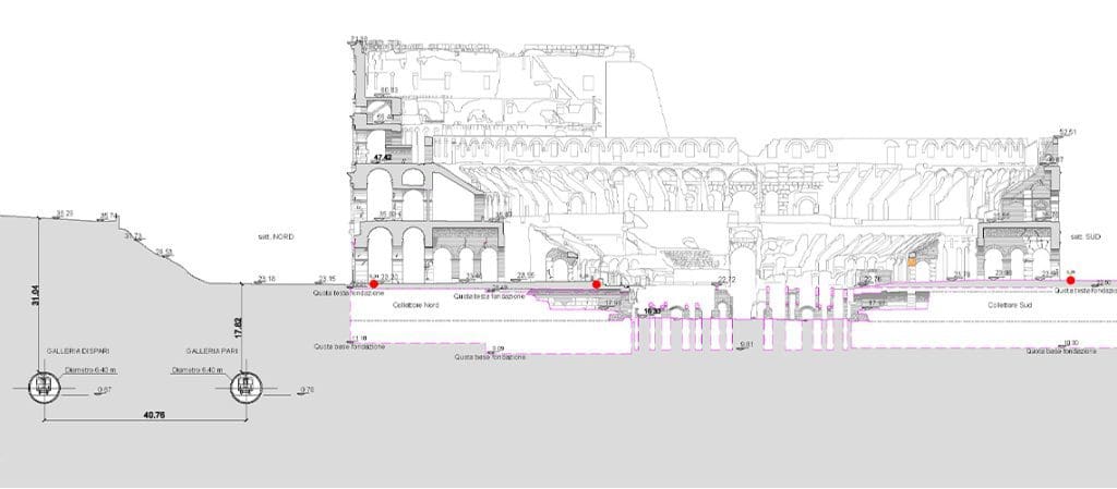
Rome metro Line C runs through the city from North-West (Della Vittoria district) to the eastern suburb and is extending beyond the Grande Raccordo Anulare.Line C has a full-run of 25,6 km and 30 stations, passing through the old town centre.The Route will be characterised by the green colour. The interchanges with the other metro […]
Bangkok Blue Line Extension Project, Contract 2 – Thailand

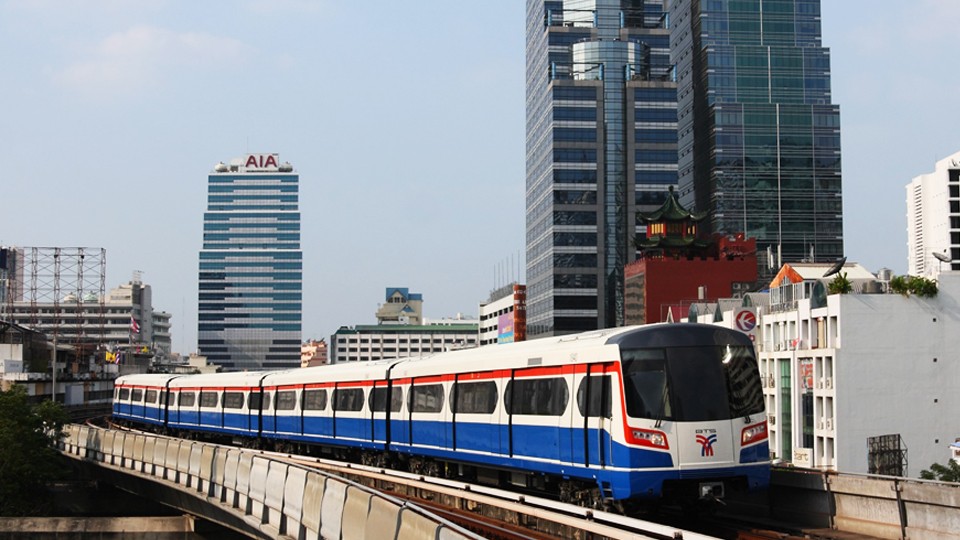
The MRT (Metropolitan Rapid Transit) Blue Line is being extended.The extension is expected to be completed in 2017 and by then the Blue Line will become a loop line around the centre of Bangkok, with the part on the western side of the Chao Praya River mainly being an elevated system and the other half […]
FAQ#116 – How do I configure a WR-Log digital node to read RS485 Sisgeo TIMED sensors?
Sisgeo digital instruments can operate in two powering modes: TIMED or ALWAYS-ON (for more information see F.A.Q.#094).A string of mixed instruments consisting of TIMED gauges and ALWAYS-ON gauges cannot work.The first thing to do is therefore to check that ALL connected instruments in your array are set to TIMED mode.You can check the powering mode […]
FAQ#094 – Which are the available powering modes for SISGEO digital sensors?
All SISGEO digital gauges can be settled in two different powering mode: The STANDARD powering mode is ALWAYS ON, so unless otherwise requested by the Customer, the sensors are settled as default in ALWAYS ON.
FAQ # 076 – ¿Por qué es necesario añadir una resistencia de terminación para el último sensor digitalizado de cada cadena RS-485?
Todos los instrumentos digitalizados SISGEO (IPI, inclinómetros, H-Nivel …) utilizan el protocolo de comunicación de serie RS-485. El protocolo RS485 contempla una resistencia de terminación. La conexión en cadena recomendada es de nodos de punto-a-punto (multipunto) como un modo BUS (línea). Estrella, anillo o multiplicar la conexión de red no se recomiendan. Los dataloggers SISGEO […]
FAQ#075 – What parameters are saved in SISGEO digital sensors? What information must the Customer provide when ordering?
All SISGEO digital sensors (e.g. IPI, BH Profile, MD Profile, LT Inclibus, Tilt-meter, RDS, H-Level, etc.) use the Modbus communication protocol over RS-485 serial. SISGEO digital sensors are connected to each other with a single signal cable. The parameters that are configured at the factory for each digital sensor are as follows: Upon confirmation of […]
FAQ # 074 – ¿Qué tipo de datalogger es necesario para leer los sensores digitalizados SISGEO?
Los sensores se leen conectando el cable final a una unidad Modbus maestro (es decir OMNIAlog o miniOMNIAlog) con interfaz RS-485 (DCE, Half duplex, sin eco) capaz de gestionar la comunicación con el protocolo de comunicación Modbus RTU SISGEO. El protocolo de comunicación de SISGEO está disponible para la liberación bajo petición. La potencia [W] […]
FAQ # 073 – ¿Cuál es el número máximo de sensores digitales (RS-485, Modbus), el número máximo de cadenas y la longitud máxima de cable en una red RS-485?
Última actualización: Octubre 2021 Todos los sensores digitalizados SISGEO utilizan una interfaz RS485 con protocolo Modbus. 1.El número máximo de sensores digitalizados en una red RS-485 son 247 (teórico) 2.El número máximo de cadenas de sensores digitalizados que es posible conectar a la unidad maestra Modbus (como OMNIAlog o miniOMNIAlog) son 4. 3. Sobre el […]


