RDS
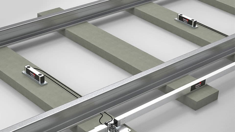
Il sistema RDS (Railway Deformation System) è un sistema di monitoraggio non convenzionale progettato da Sisgeo per il monitoraggio automatico della deformazione longitudinale delle rotaie e dell’inclinazione del binario (o torsione del binario).
FLX-Rail
FLX-Rail® è un misuratore di fessure ad alta precisione progettato per misurare in modo automatico e continuo la deformazione verticale massima delle rotaie ad ogni passaggio del treno.
Metropolitana di Roma – linea C
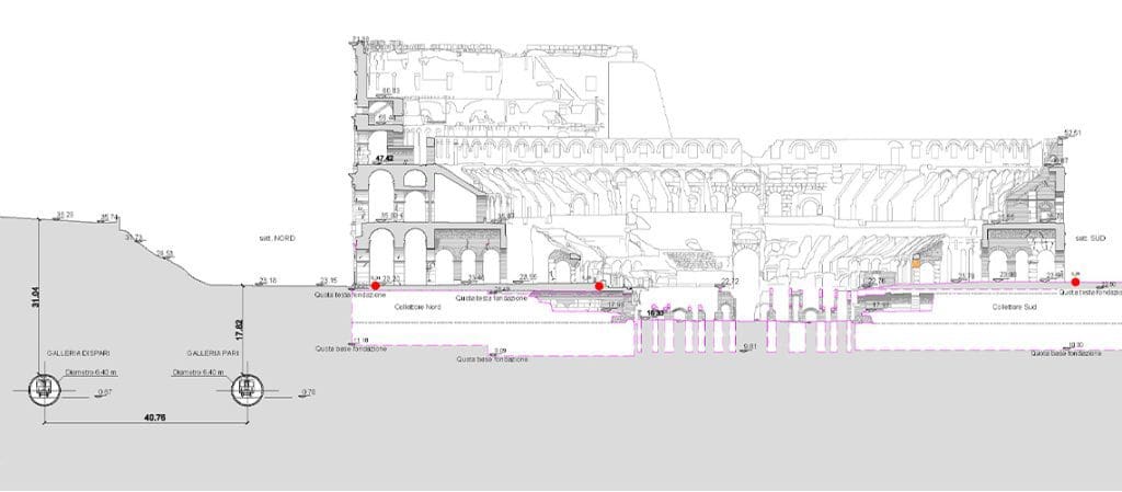
Rome metro Line C runs through the city from North-West (Della Vittoria district) to the eastern suburb and is extending beyond the Grande Raccordo Anulare.Line C has a full-run of 25,6 km and 30 stations, passing through the old town centre.The Route will be characterised by the green colour. The interchanges with the other metro […]
Metropolitana Linea 4 – Lorenteggio – Linate Monitoraggio sotto-attraversamento binari ferroviari RFI tra le stazioni Forlanini Q.RE e Forlanini FS
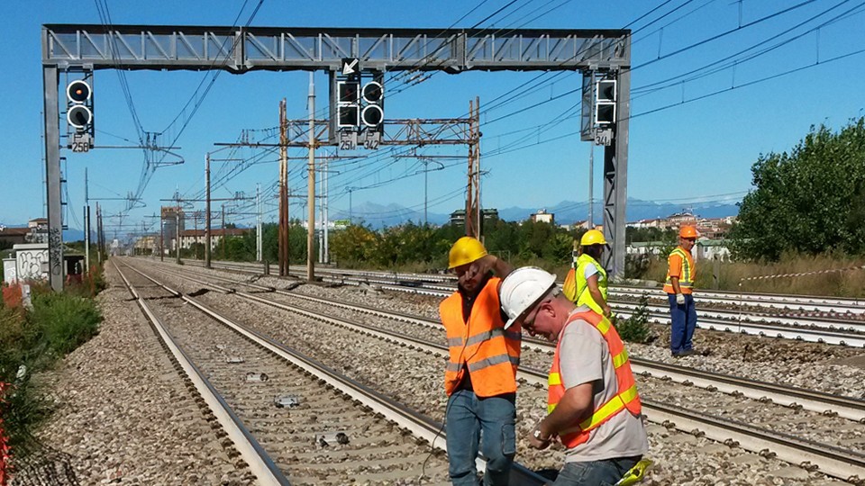
Gli obiettivi principali della realizzazione della M4 sono: realizzare una nuova linea diametrale da Est a Ovest, per collegare attraverso il centro storico alcune aree urbane altamente popolate che non sono ben servite dalla rete di trasporto pubblico; interconnettersi con l’intero sistema ferroviario, urbano e regionale; per realizzare un collegamento diretto tra il centro città […]
Fermata Forlanini passante – Monitoraggio sottopasso nord e sud
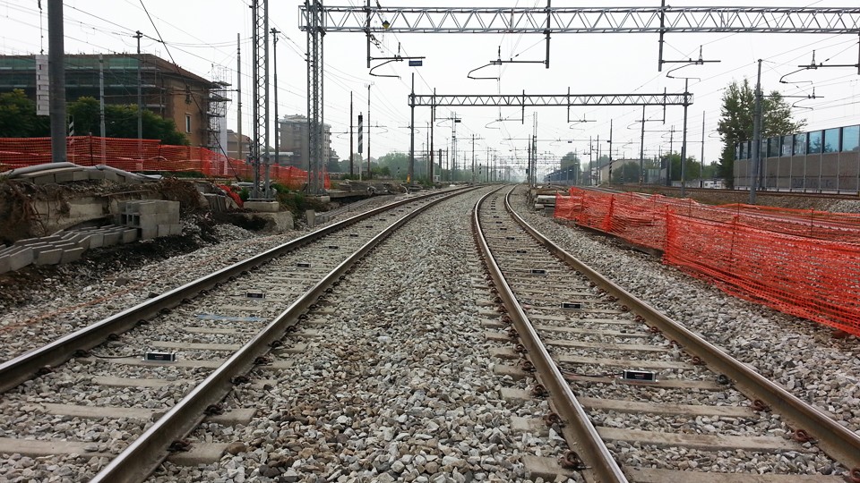
The realization of the railway station Forlanini FS is connected to the realization of the M4 Metro of Milan (line 4). Forlanini FS station, which has been opened in May 2015, allows to connect the system of the suburban railway lines (S5, S6 and S9) to Linate airport, thanks to line M4.During the rails translation […]
FAQ#110 – What’s the purpose of the linear and polynomial factors written in the Calibration Reports?
Utilize the Linear Sensitivity Factors (A, B) and Ploynomial Sensitivity Factors (A, B, C, D) of the Calibration Reports permit to obtain readings in engineerig units with a maximum error as for the Calibration Report. In the case of analogue gauges, the factors shall be applied on the electrical readings (i.e. mA, mV, digit, etc…) […]
FAQ#095 – How long does a chain of digital sensors take to be read?
It mainly depends from the powering mode of the gauges (refer to FAQ#094 for the description of the powering modes). AN EXAMPLE WILL BETTER CLARIFY THE ANSWER. In a batch of 240 gauges, unless otherwise requested by the Customer, the addresses are settled from #001 up to #240. In a borehole is installed a chain of 30 […]
FAQ#094 – Which are the available powering modes for SISGEO digital sensors?
All SISGEO digital gauges can be settled in two different powering mode: The STANDARD powering mode is ALWAYS ON, so unless otherwise requested by the Customer, the sensors are settled as default in ALWAYS ON.
FAQ#077 – Which are the maximum cable lengths from instrument to datalogger?
The cable lengths depend from many factors, first of all installation and cable protections (screen, earth, etc…). Assuming that instruments are installed in a workmanlike, for the maximum cable lengths should be followed the next suggestions: DIGITAL INSTRUMENTS: see FAQ#73 ANALOGUE INSTRUMENTS: see both downloadable documents.
FAQ#076 – Perchè è necessario aggiungere una resistenza di terminazione sull’ultimo sensore digitalizzato di ogni catena RS-485?
Tutti i sensori digitalizzati SISGEO (IPI, Tilmetri, H-Level, RDS ) usano il protocollo di comunicazione seriale RS-485. Il protocollo RS-485 contempla una resistenza di terminazione. Il collegamento raccomandato per una catena è il “punto-punto” (multidropped) in modalità bus (linea). Collegamenti a “stella”, ad“anello” o multipli non sono raccomandati. I datalogger SISGEO sono già predisposti con […]
FAQ#075 – What parameters are saved in SISGEO digital sensors? What information must the Customer provide when ordering?
All SISGEO digital sensors (e.g. IPI, BH Profile, MD Profile, LT Inclibus, Tilt-meter, RDS, H-Level, etc.) use the Modbus communication protocol over RS-485 serial. SISGEO digital sensors are connected to each other with a single signal cable. The parameters that are configured at the factory for each digital sensor are as follows: Upon confirmation of […]
FAQ#073 – Qual è il numero massimo di sensori digitalizzati (RS-485, modbus), il numero massimo di catene e la distanza massima del cavo di collegamento in una rete RS-485?
Ultimo aggiornamento: ottobre 2021 Tutti i sensori digitalizzati SISGEO utilizzano il una interfaccia RS485 con protocollo Modbus. 1. Il numero massimo di sensori digitalizzati in una rete RS-485 è 247 (teorico). 2. Il numero massimo di catene di sensori digitalizzati collegabili ad un Modbus master (OMNIAlog e miniOMNIAlog) è 4. 3. Per le distanze massime […]