RDS
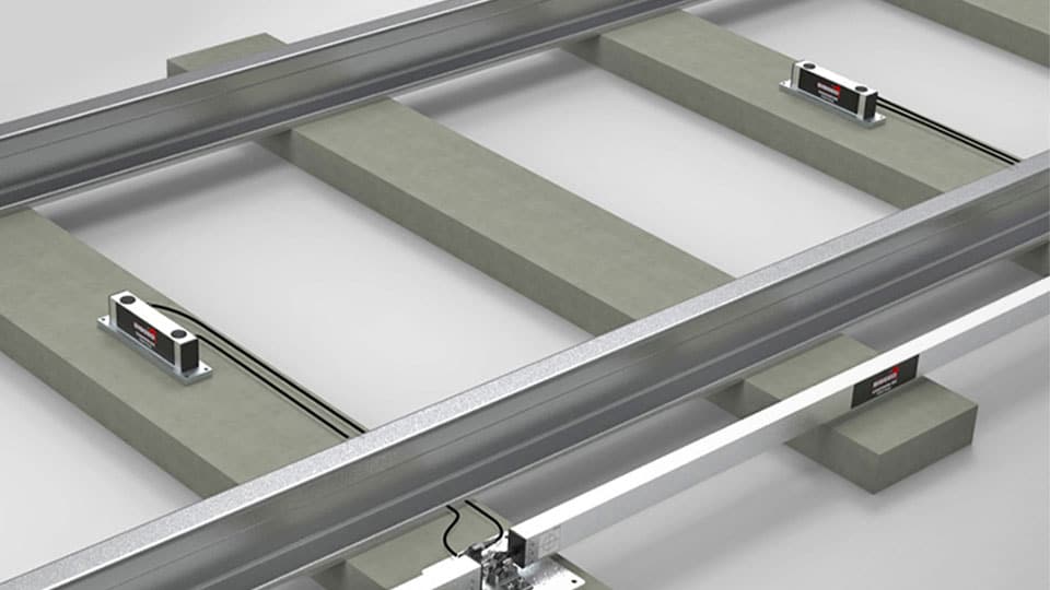
El sistema de deformación ferroviaria RDS es un sistema de monitorización no convencional diseñado por Sisgeo para la monitorización automática de la deformación longitudinal de las vías férreas y del peralte (o torsión de la vía).
FLX-Rail
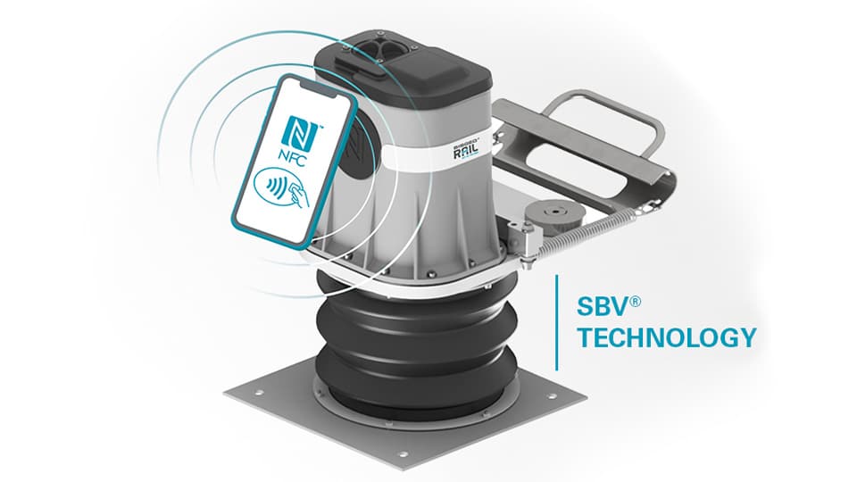
FLX-Rail® es un medidor de holguras de alta precisión diseñado para medir de forma automática y continua la deformación vertical máxima del carril durante cada paso de tren.
Rome Underground – Line C – Italy
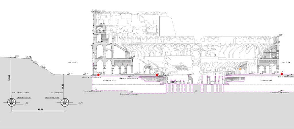
Rome metro Line C runs through the city from North-West (Della Vittoria district) to the eastern suburb and is extending beyond the Grande Raccordo Anulare.Line C has a full-run of 25,6 km and 30 stations, passing through the old town centre.The Route will be characterised by the green colour. The interchanges with the other metro […]
Milan Metro Line 4 – Lorenteggio–Linate – Monitoring of the underpass of railway trails RFI between stations “Forlanini Q.RE” and “Forlanini FS” – Italy
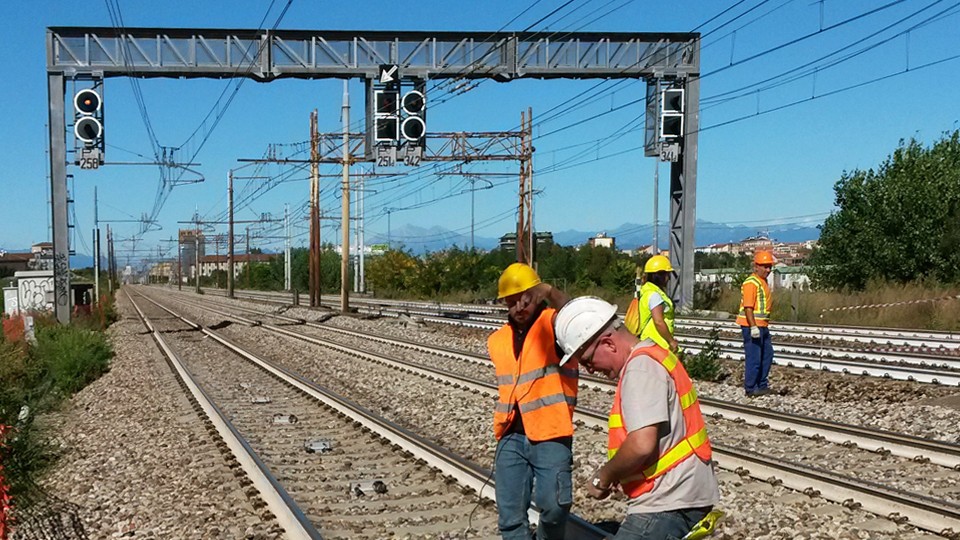
The main aims of the M4 realization are: to realize a new diametrical line from East to West, in order to connect through the historical center some highly populated urban areas that are not well served by the network of public transport; to interconnect with the whole railway system, urban and regional; to realize a […]
Milano, Forlanini Stop Bypass – Monitoring of Northern and Southern Underpass – Italy
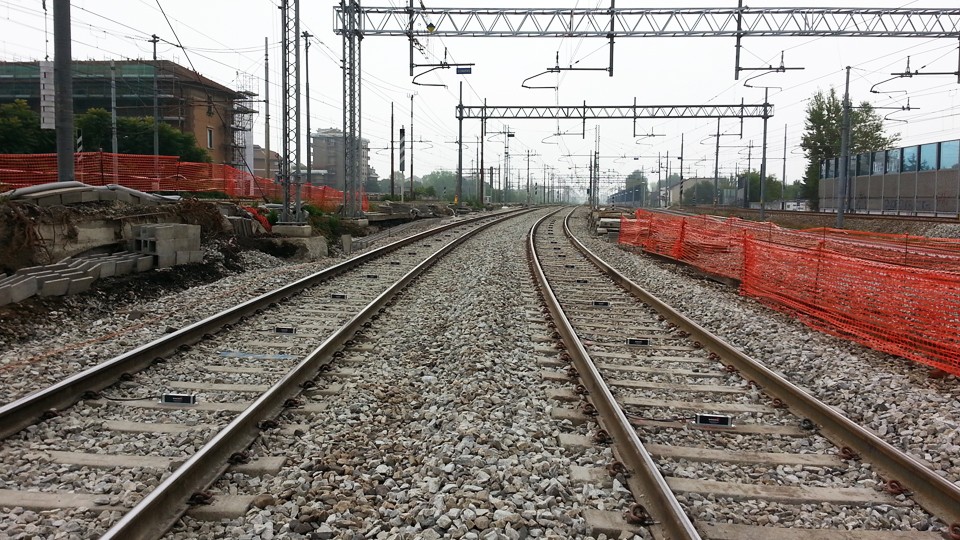
The realization of the railway station Forlanini FS is connected to the realization of the M4 Metro of Milan (line 4). Forlanini FS station, which has been opened in May 2015, allows to connect the system of the suburban railway lines (S5, S6 and S9) to Linate airport, thanks to line M4.During the rails translation […]
FAQ#110 – What’s the purpose of the linear and polynomial factors written in the Calibration Reports?
Utilize the Linear Sensitivity Factors (A, B) and Ploynomial Sensitivity Factors (A, B, C, D) of the Calibration Reports permit to obtain readings in engineerig units with a maximum error as for the Calibration Report. In the case of analogue gauges, the factors shall be applied on the electrical readings (i.e. mA, mV, digit, etc…) […]
FAQ#095 – How long does a chain of digital sensors take to be read?
It mainly depends from the powering mode of the gauges (refer to FAQ#094 for the description of the powering modes). AN EXAMPLE WILL BETTER CLARIFY THE ANSWER. In a batch of 240 gauges, unless otherwise requested by the Customer, the addresses are settled from #001 up to #240. In a borehole is installed a chain of 30 […]
FAQ#094 – Which are the available powering modes for SISGEO digital sensors?
All SISGEO digital gauges can be settled in two different powering mode: The STANDARD powering mode is ALWAYS ON, so unless otherwise requested by the Customer, the sensors are settled as default in ALWAYS ON.
FAQ#077 – Which are the maximum cable lengths from instrument to datalogger?
The cable lengths depend from many factors, first of all installation and cable protections (screen, earth, etc…). Assuming that instruments are installed in a workmanlike, for the maximum cable lengths should be followed the next suggestions: DIGITAL INSTRUMENTS: see FAQ#73 ANALOGUE INSTRUMENTS: see both downloadable documents.
FAQ # 076 – ¿Por qué es necesario añadir una resistencia de terminación para el último sensor digitalizado de cada cadena RS-485?
Todos los instrumentos digitalizados SISGEO (IPI, inclinómetros, H-Nivel …) utilizan el protocolo de comunicación de serie RS-485. El protocolo RS485 contempla una resistencia de terminación. La conexión en cadena recomendada es de nodos de punto-a-punto (multipunto) como un modo BUS (línea). Estrella, anillo o multiplicar la conexión de red no se recomiendan. Los dataloggers SISGEO […]
FAQ#075 – What parameters are saved in SISGEO digital sensors? What information must the Customer provide when ordering?
All SISGEO digital sensors (e.g. IPI, BH Profile, MD Profile, LT Inclibus, Tilt-meter, RDS, H-Level, etc.) use the Modbus communication protocol over RS-485 serial. SISGEO digital sensors are connected to each other with a single signal cable. The parameters that are configured at the factory for each digital sensor are as follows: Upon confirmation of […]
FAQ # 073 – ¿Cuál es el número máximo de sensores digitales (RS-485, Modbus), el número máximo de cadenas y la longitud máxima de cable en una red RS-485?
Última actualización: Octubre 2021 Todos los sensores digitalizados SISGEO utilizan una interfaz RS485 con protocolo Modbus. 1.El número máximo de sensores digitalizados en una red RS-485 son 247 (teórico) 2.El número máximo de cadenas de sensores digitalizados que es posible conectar a la unidad maestra Modbus (como OMNIAlog o miniOMNIAlog) son 4. 3. Sobre el […]