Hydraulische Druckmessdosen
Codes der Referenzprodukte: L111, PK45H, P252A, TUNY
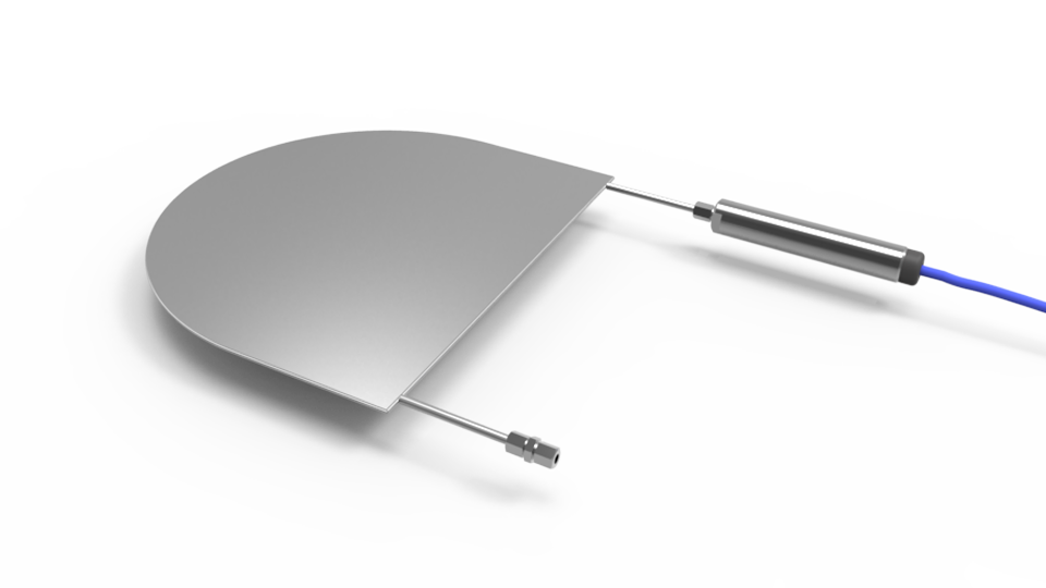
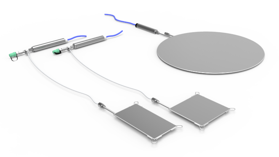
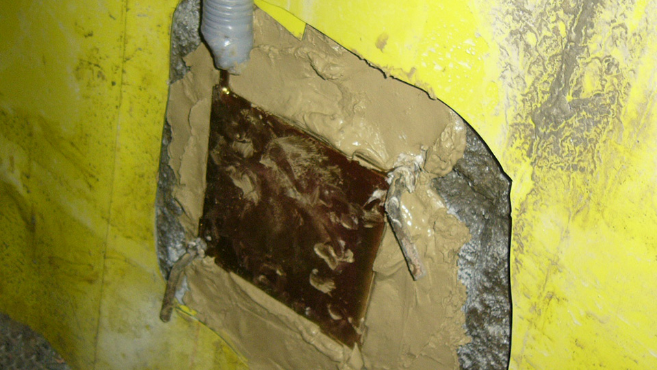
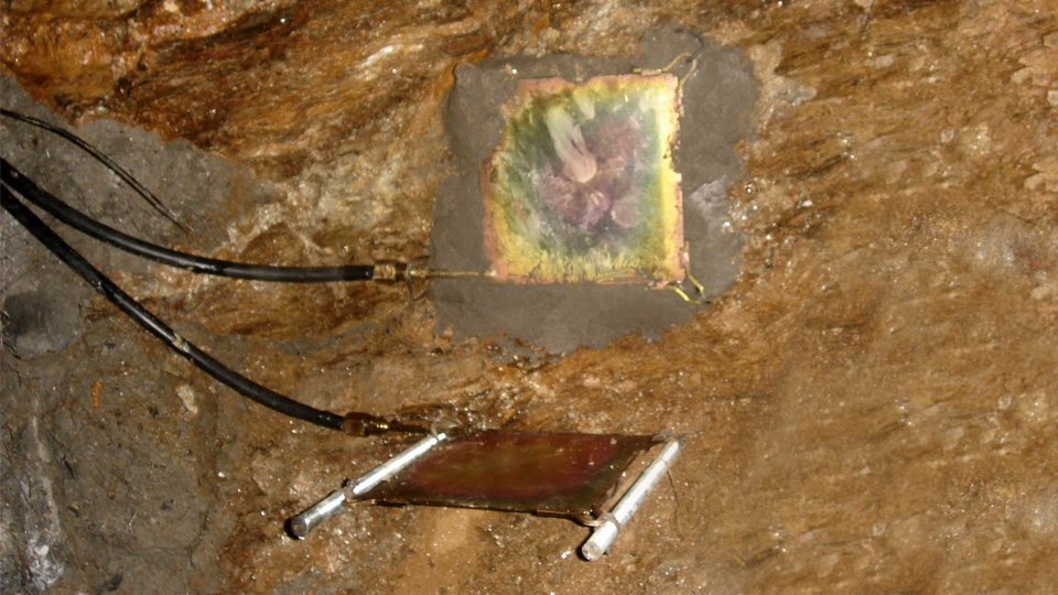
Hydraulic pressure cells are designed to measure stress in mass concrete or placed at the interface between the structure and the wall of excavation.
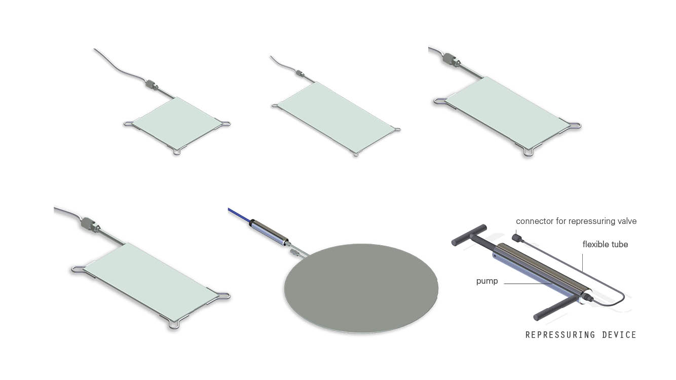
The pressure pad consists of two steel plates welded together around their periphery and spaced apart by a narrow cavity saturated under vacuum with de-aired oil which guarantee maximum rigidity. A length of high-pressure rilsan tubing connects the cavity of the pressure pad to the pressure transducer.
A repressurizing device is available for expanding the cell after the concrete has cured. Readings are obtained with portable readout units or dataloggers.
Resistive pressure transducer sensor is a spin off from thick film technology using the piezo-resistive characteristic of specific resistive inks. Resistors, formed using screen printing techniques, are deposited on a deformable ceramic diaphragm substrate to form strain gauge arrays. Strain changes from external loads applied to the deformable ceramic diaphragm result in resistance changes of the strain gauge arrays.
The electric signal from the strain gauge arrays is directly proportional to the stress applied to the diaphragm. Sensor is constructed of a ceramic, analogous to a crystal structure, to form a pressure diaphragm chemically inert with near perfect mechanical characteristics. Screen printed resistors are deposited onto the diaphragm to form a 4 arms Wheatstone bridge.
A fixed excitation voltage is applied to one diagonal of the circuit. Strains experienced by the diaphragm will change the values of the individual resistors within the Wheatstone bridge resulting in a bridge unbalance. This unbalance produce an output signal from the other diagonal of the Wheatstone bridge, directly proportional to the applied stress.
An electronic board converts this signal into 4-20 mA suitable for transmission over long distances to remote readouts or to data acquisition systems.
Vibrating wire transducer is essentially composed by a taut wire clamped at its ends and tensioned so that it is free to vibrate at its natural frequency. The frequency of vibration varies with the wire tension and thus small relative movements between the two end clamps.
With VW transducers frequencies rather than voltage levels are measured, so a dedicated readout/datalogger must be used to measure the resonant frequency. These ones excites the VW transducer, measures the response, performs some calculations on the response, and returns the result.
SISGEO VW transducer uses ‚pluck and read‘ method and not ‚auto resonant‘ method; when the readout/datalogger plucks the wire a magnetic attraction is created to the coil and the wire start to vibrate and it causes an alternating voltage of the same frequency of the natural frequency of the wire; the voltage signal is transmitted on the cable and read from the readout/datalogger.
VW transducers have a reputation for long expected life and long-term stability.
Messen Mit


Datenblatt
Handbuch
Datenverarbeitung
Faq
Datenblatt
Handbuch
Datenverarbeitung
Faq
Verwandte
Produkte