Lower Chatkal Hydroelectric Plant

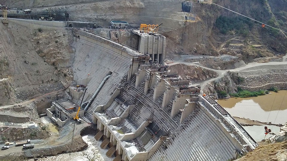
New dam under construction Uzbekistan The Lower Chatkal Hydroelectric Plant, currently under construction in Uzbekistan, is based on an RCC (Roller Compacted Concrete) dam. Given the scale and strategic importance of the project, the design team required a comprehensive and reliable monitoring system to ensure structural safety and operational efficiency throughout construction and during long-term […]
Elektronisches Lotmesssystem – Telependulum

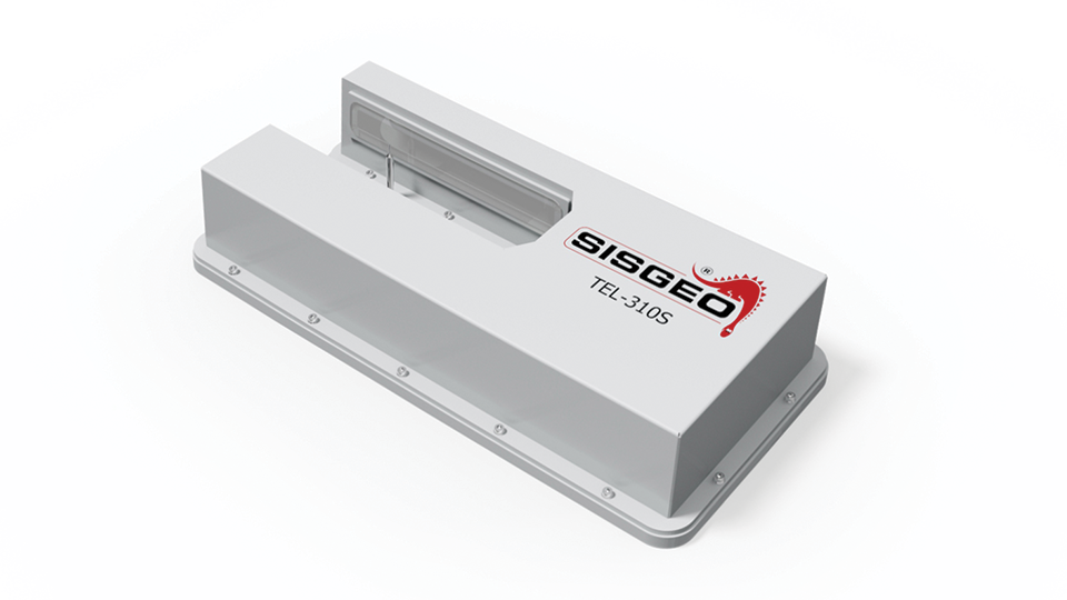
Codes der Referenzprodukte: TEL310, TEL-310, TEL310S, TEL-310S TEL-310S Telecoordinometer (Telependulum) is designed for automatic readings of the coordinates of the pendulum plumb lines (direct or inverted). TEL-310S is characterized by high resolution and the possibility of measuring many steel wire simultaneously. Moreover this instrument offers auto-diagnostic functions for measurements validation through a built-in high performance […]
Cerro del Águila Hydroelectric power plant

The Cerro del Águila HPP is a hydroelectric power plant located on the Mantaro River in the districts of Colcabamba and Surcubamba, within the Province of Tayacaja and Region of Huancavelica, in central Peru. The Project will be located downstream of the Mantaro hydroelectric complex. The Project is an independent activity from the Mantaro hydroelectric […]
Rome Underground – Line C – Italy

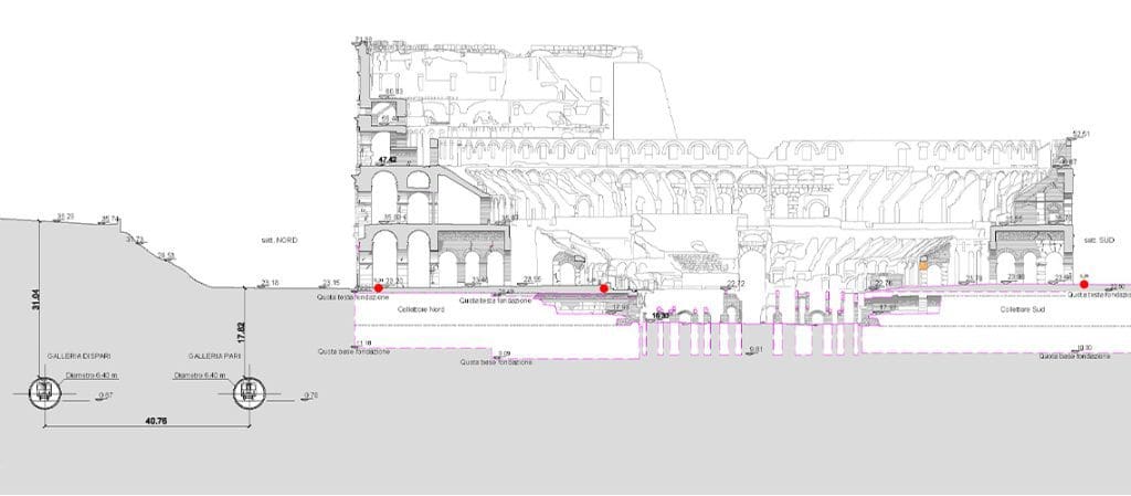
Rome metro Line C runs through the city from North-West (Della Vittoria district) to the eastern suburb and is extending beyond the Grande Raccordo Anulare.Line C has a full-run of 25,6 km and 30 stations, passing through the old town centre.The Route will be characterised by the green colour. The interchanges with the other metro […]
FAQ#038 – Do I have to power the TEL-310S before start to set-up and use it?
If the TEL-310S was supplied 2 or more month before, will be better to power it for 8 hours before starting to set-up and use it. This is to recharge the back-up battery that give troubles if it is completely discharged.
FAQ#009 – Can the TEL-310S functioning be influenced from atmospheric conditions?
Any factor (water, mud etc.) that could dirty the internal part of the “SUS” optical sensor unit’s cover can influence the TEL-310S correct functioning. So it is essential to protect properly the “SUS” optical sensor unit from weather conditions, leaving anyway the access possibility for cleaning/maintenance. In any case, TEL-310S has an auto-diagnostics able to […]
FAQ#008 – What is the 0TEL310CAL0 calibration/mounting kit and what is it for?
The 0TEL310CAL0 kit includes a drilling template for the wall where the “ANS” support will be placed, and a template to be placed on the “SUS” optical sensor unit for a possible functional check on field (pendulum’s wire simulation).
FAQ#007 – Are the TEL-310S CUS control unit and the PWS power unit supplied with the fixing kit?
No kit is needed. The “CUS” and “PWS” units are placed in aluminum boxes ready to be fixed on the wall through four M6 screws (not included).
FAQ#006 – Is it possible to use the ANS adjustable support for the pendulum optical manual readout (coordinometer)?
The pendulum readout fixing plate has four holes so it can be fixed, through screws, to the “ANS” adjustable support.
FAQ#005 – Is it possible to fix the ANS adjustable support to the floor?
Since the “ANS” support is articulated, it can be fixed to the floor; this can be useful in case the pendulum’s wire is too far from the walls.
FAQ#004 – Is it possible to place the SUS optical sensor unit with the X axis perpendicular to the wall where the ANS support is fixed?
The TEL-310S telecoordinometer has the following measuring range: To use the “ANS” adjustable support you must have the “X” axis parallel to the wall: so it is not possible to fix the “SUS” optical sensor unit perpendicular to the wall using the “ANS” adjustable support.
FAQ#003 – Which are the needed conditions to use the ANS adjustable support for TEL-310S if you need to monitor the direct pendulum’s wire?
To fix the “SUS” optical sensor unit through the “ANS” support, it is necessary that the direct pendulum’s wire is at a distance of d=230 mm. from the wall. To achieve that, the direct pendulum’s tank has to be placed at a distance of D=20 mm. from the wall: in this way is guaranteed that […]


