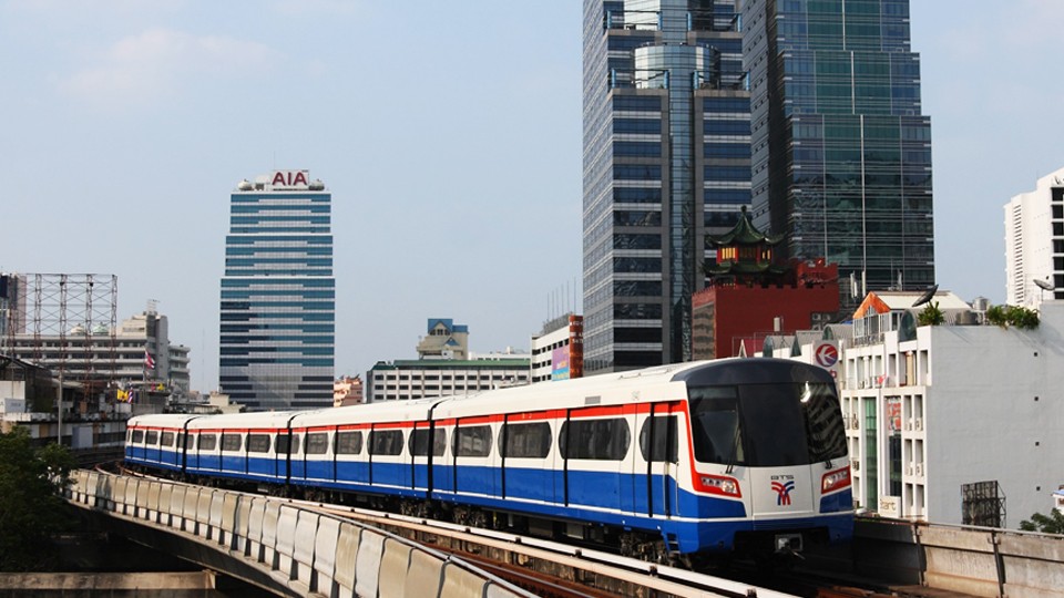
Bangkok Blue Line Extension Project, Contract 2 – Thailand

The MRT (Metropolitan Rapid Transit) Blue Line is being extended.The extension is expected to be completed in 2017 and by then the Blue Line will become a loop line around the centre of Bangkok, with the part on the western side of the Chao Praya River mainly being an elevated system and the other half […]
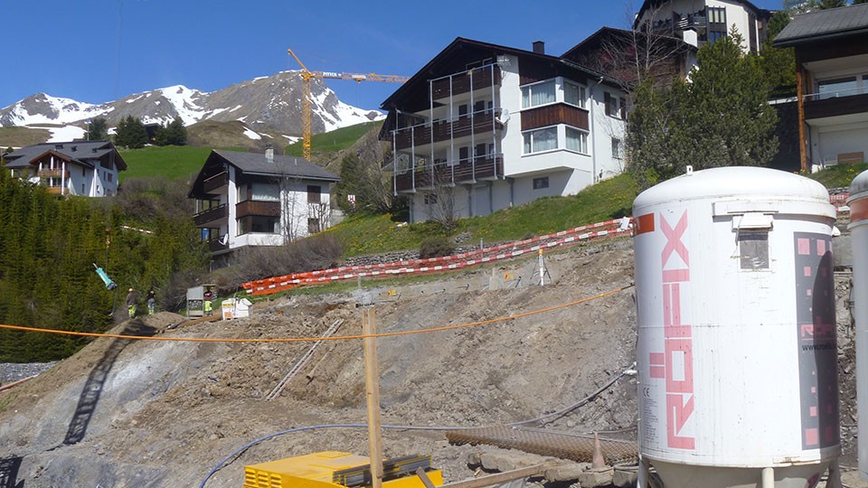
Arosa Schafisgade project – new touristic resort – Switzerland

The Arosa Schafisgade project includes construction of three houses with each six luxury apartments. The houses are located in a potential unstable slope. During excavation work adjacent houses above the new built ones had to be monitored geodetically. Between the new excavation and the existing houses borehole inclinometers had been drilled and monitored to detect […]
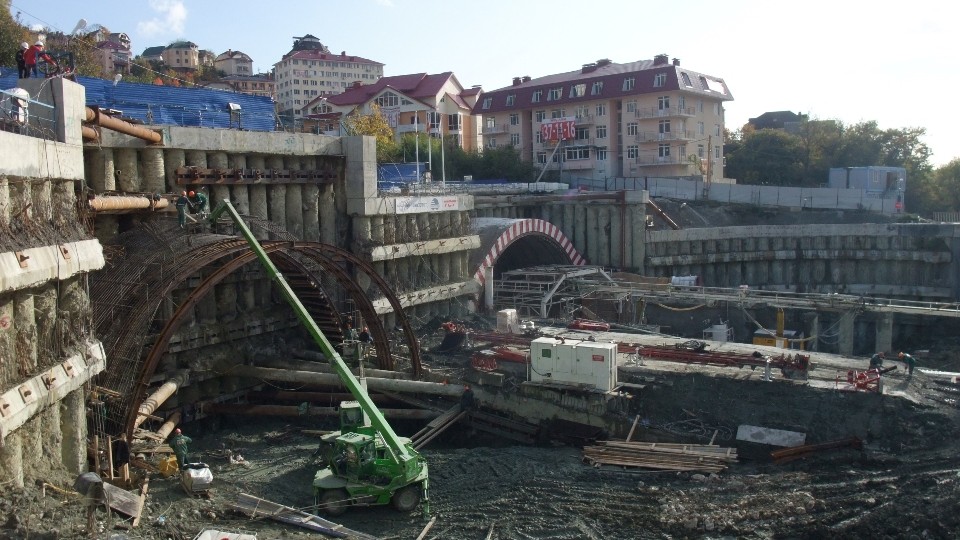
Monitoring works for the 2014 Sochi Winter Olympic Games – Russia

Sisgeo, thanks to the collaboration with its Russian partners AGT Systems and GPIKO, furnished and installed all the equipments necessary to monitor the most important road and railway works that are under construction in Sochi area, that is the neural centre of 2014 Winter Olympics.The monitored works are: retaining walls for the protection of roads, […]
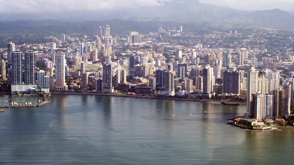
Cleaning-up project of Panama City and Bay

The cleaning-up project of Panama City and Bay includes: Construction of Health Service networks Construction and rehabilitation of Collectors and Drive lines Interceptor system Plant for wastewater treatment. These elements will be developed to collect, transport and treat wastewater of Panama City which is currently discharged directly into the bay or rivers and streams in […]
FAQ#116 – How do I configure a WR-Log digital node to read RS485 Sisgeo TIMED sensors?
Sisgeo digital instruments can operate in two powering modes: TIMED or ALWAYS-ON (for more information see F.A.Q.#094).A string of mixed instruments consisting of TIMED gauges and ALWAYS-ON gauges cannot work.The first thing to do is therefore to check that ALL connected instruments in your array are set to TIMED mode.You can check the powering mode […]
FAQ#111 – Why I cannot read correctly my 4-20mA current loop gauge?
It could be a problem connected to the power supply given by the readout or logger. When the power supply is in the current loop (2-wire gauge) it is necessary to consider the effect of voltage drop across the shunt resistor on the voltage applied to the gauge. For example, suppose a 4-20mA gauge requires […]
FAQ#094 – Which are the available powering modes for SISGEO digital sensors?
All SISGEO digital gauges can be settled in two different powering mode: The STANDARD powering mode is ALWAYS ON, so unless otherwise requested by the Customer, the sensors are settled as default in ALWAYS ON.
FAQ # 076 – ¿Por qué es necesario añadir una resistencia de terminación para el último sensor digitalizado de cada cadena RS-485?
Todos los instrumentos digitalizados SISGEO (IPI, inclinómetros, H-Nivel …) utilizan el protocolo de comunicación de serie RS-485. El protocolo RS485 contempla una resistencia de terminación. La conexión en cadena recomendada es de nodos de punto-a-punto (multipunto) como un modo BUS (línea). Estrella, anillo o multiplicar la conexión de red no se recomiendan. Los dataloggers SISGEO […]
FAQ#075 – What parameters are saved in SISGEO digital sensors? What information must the Customer provide when ordering?
All SISGEO digital sensors (e.g. IPI, BH Profile, MD Profile, LT Inclibus, Tilt-meter, RDS, H-Level, etc.) use the Modbus communication protocol over RS-485 serial. SISGEO digital sensors are connected to each other with a single signal cable. The parameters that are configured at the factory for each digital sensor are as follows: Upon confirmation of […]
FAQ # 074 – ¿Qué tipo de datalogger es necesario para leer los sensores digitalizados SISGEO?
Los sensores se leen conectando el cable final a una unidad Modbus maestro (es decir OMNIAlog o miniOMNIAlog) con interfaz RS-485 (DCE, Half duplex, sin eco) capaz de gestionar la comunicación con el protocolo de comunicación Modbus RTU SISGEO. El protocolo de comunicación de SISGEO está disponible para la liberación bajo petición. La potencia [W] […]
FAQ # 073 – ¿Cuál es el número máximo de sensores digitales (RS-485, Modbus), el número máximo de cadenas y la longitud máxima de cable en una red RS-485?
Última actualización: Octubre 2021 Todos los sensores digitalizados SISGEO utilizan una interfaz RS485 con protocolo Modbus. 1.El número máximo de sensores digitalizados en una red RS-485 son 247 (teórico) 2.El número máximo de cadenas de sensores digitalizados que es posible conectar a la unidad maestra Modbus (como OMNIAlog o miniOMNIAlog) son 4. 3. Sobre el […]


