Brunt Road LXR – new bridge monitoring
Sisgeo supplied instrumentation for the monitoring of a new road bridge over the rail line at Brunt Road in Beaconsfield, Australia. The Victorian Government aims to eliminate 110 dangerous and congested level crossings across Melbourne by the year 2030, marking the largest initiative of its kind in the history of Victoria. In fact, removing this […]
360° LT-Inclibus array
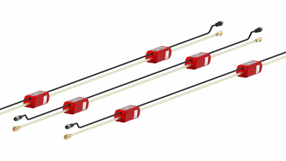
Códigos de referencia de los productos: LTIBThe LT-Inclibus is able to monitor local tilting along a line, assuring the alignment, distance and measuring axis orientation between the gauges. The standard segment is composed by a 2m fibre glass rod with two waterproof gauges, 1m spaced. It is possible to have one or four gauges on […]
FAQ#116 – How do I configure a WR-Log digital node to read RS485 Sisgeo TIMED sensors?
Sisgeo digital instruments can operate in two powering modes: TIMED or ALWAYS-ON (for more information see F.A.Q.#094).A string of mixed instruments consisting of TIMED gauges and ALWAYS-ON gauges cannot work.The first thing to do is therefore to check that ALL connected instruments in your array are set to TIMED mode.You can check the powering mode […]
FAQ#110 – What’s the purpose of the linear and polynomial factors written in the Calibration Reports?
Utilize the Linear Sensitivity Factors (A, B) and Ploynomial Sensitivity Factors (A, B, C, D) of the Calibration Reports permit to obtain readings in engineerig units with a maximum error as for the Calibration Report. In the case of analogue gauges, the factors shall be applied on the electrical readings (i.e. mA, mV, digit, etc…) […]
FAQ#095 – How long does a chain of digital sensors take to be read?
It mainly depends from the powering mode of the gauges (refer to FAQ#094 for the description of the powering modes). AN EXAMPLE WILL BETTER CLARIFY THE ANSWER. In a batch of 240 gauges, unless otherwise requested by the Customer, the addresses are settled from #001 up to #240. In a borehole is installed a chain of 30 […]
FAQ#094 – Which are the available powering modes for SISGEO digital sensors?
All SISGEO digital gauges can be settled in two different powering mode: The STANDARD powering mode is ALWAYS ON, so unless otherwise requested by the Customer, the sensors are settled as default in ALWAYS ON.
FAQ#077 – Which are the maximum cable lengths from instrument to datalogger?
The cable lengths depend from many factors, first of all installation and cable protections (screen, earth, etc…). Assuming that instruments are installed in a workmanlike, for the maximum cable lengths should be followed the next suggestions: DIGITAL INSTRUMENTS: see FAQ#73 ANALOGUE INSTRUMENTS: see both downloadable documents.
FAQ # 076 – ¿Por qué es necesario añadir una resistencia de terminación para el último sensor digitalizado de cada cadena RS-485?
Todos los instrumentos digitalizados SISGEO (IPI, inclinómetros, H-Nivel …) utilizan el protocolo de comunicación de serie RS-485. El protocolo RS485 contempla una resistencia de terminación. La conexión en cadena recomendada es de nodos de punto-a-punto (multipunto) como un modo BUS (línea). Estrella, anillo o multiplicar la conexión de red no se recomiendan. Los dataloggers SISGEO […]
FAQ#075 – What parameters are saved in SISGEO digital sensors? What information must the Customer provide when ordering?
All SISGEO digital sensors (e.g. IPI, BH Profile, MD Profile, LT Inclibus, Tilt-meter, RDS, H-Level, etc.) use the Modbus communication protocol over RS-485 serial. SISGEO digital sensors are connected to each other with a single signal cable. The parameters that are configured at the factory for each digital sensor are as follows: Upon confirmation of […]
FAQ # 073 – ¿Cuál es el número máximo de sensores digitales (RS-485, Modbus), el número máximo de cadenas y la longitud máxima de cable en una red RS-485?
Última actualización: Octubre 2021 Todos los sensores digitalizados SISGEO utilizan una interfaz RS485 con protocolo Modbus. 1.El número máximo de sensores digitalizados en una red RS-485 son 247 (teórico) 2.El número máximo de cadenas de sensores digitalizados que es posible conectar a la unidad maestra Modbus (como OMNIAlog o miniOMNIAlog) son 4. 3. Sobre el […]