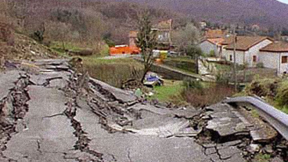
Molunghi landslide monitoring, Italy

Study and monitoring of Molunghi landslide The monitoring project of Molunghi landslide is the result of the cooperation between the Comune di Calice al Cornoviglio and the Road Department of La Spezia Province and it is began in consequence of the instability of both the provincial street and part of Monlunghi di Mezzo inhabitat during […]
FAQ#116 – How do I configure a WR-Log digital node to read RS485 Sisgeo TIMED sensors?
Sisgeo digital instruments can operate in two powering modes: TIMED or ALWAYS-ON (for more information see F.A.Q.#094).A string of mixed instruments consisting of TIMED gauges and ALWAYS-ON gauges cannot work.The first thing to do is therefore to check that ALL connected instruments in your array are set to TIMED mode.You can check the powering mode […]
FAQ#111 – Why I cannot read correctly my 4-20mA current loop gauge?
It could be a problem connected to the power supply given by the readout or logger. When the power supply is in the current loop (2-wire gauge) it is necessary to consider the effect of voltage drop across the shunt resistor on the voltage applied to the gauge. For example, suppose a 4-20mA gauge requires […]
FAQ#110 – What’s the purpose of the linear and polynomial factors written in the Calibration Reports?
Utilize the Linear Sensitivity Factors (A, B) and Ploynomial Sensitivity Factors (A, B, C, D) of the Calibration Reports permit to obtain readings in engineerig units with a maximum error as for the Calibration Report. In the case of analogue gauges, the factors shall be applied on the electrical readings (i.e. mA, mV, digit, etc…) […]
FAQ#095 – How long does a chain of digital sensors take to be read?
It mainly depends from the powering mode of the gauges (refer to FAQ#094 for the description of the powering modes). AN EXAMPLE WILL BETTER CLARIFY THE ANSWER. In a batch of 240 gauges, unless otherwise requested by the Customer, the addresses are settled from #001 up to #240. In a borehole is installed a chain of 30 […]
FAQ#094 – Which are the available powering modes for SISGEO digital sensors?
All SISGEO digital gauges can be settled in two different powering mode: The STANDARD powering mode is ALWAYS ON, so unless otherwise requested by the Customer, the sensors are settled as default in ALWAYS ON.
FAQ#087 – Could the IPI, BH Profile and DEX probes have problems in frozen water?
Sisgeo suggest that frozen water within the inclinometer casings is to be avoided due to following reasons: – Ice within the casing will affect functionality of the systems by blocking the individual probes;– Mechanical damages can occur to the probes, but also to the inclinometer casing due to the expansion of frozen water In any […]
FAQ#077 – Which are the maximum cable lengths from instrument to datalogger?
The cable lengths depend from many factors, first of all installation and cable protections (screen, earth, etc…). Assuming that instruments are installed in a workmanlike, for the maximum cable lengths should be followed the next suggestions: DIGITAL INSTRUMENTS: see FAQ#73 ANALOGUE INSTRUMENTS: see both downloadable documents.
FAQ # 076 – ¿Por qué es necesario añadir una resistencia de terminación para el último sensor digitalizado de cada cadena RS-485?
Todos los instrumentos digitalizados SISGEO (IPI, inclinómetros, H-Nivel …) utilizan el protocolo de comunicación de serie RS-485. El protocolo RS485 contempla una resistencia de terminación. La conexión en cadena recomendada es de nodos de punto-a-punto (multipunto) como un modo BUS (línea). Estrella, anillo o multiplicar la conexión de red no se recomiendan. Los dataloggers SISGEO […]
FAQ#075 – What parameters are saved in SISGEO digital sensors? What information must the Customer provide when ordering?
All SISGEO digital sensors (e.g. IPI, BH Profile, MD Profile, LT Inclibus, Tilt-meter, RDS, H-Level, etc.) use the Modbus communication protocol over RS-485 serial. SISGEO digital sensors are connected to each other with a single signal cable. The parameters that are configured at the factory for each digital sensor are as follows: Upon confirmation of […]
FAQ # 074 – ¿Qué tipo de datalogger es necesario para leer los sensores digitalizados SISGEO?
Los sensores se leen conectando el cable final a una unidad Modbus maestro (es decir OMNIAlog o miniOMNIAlog) con interfaz RS-485 (DCE, Half duplex, sin eco) capaz de gestionar la comunicación con el protocolo de comunicación Modbus RTU SISGEO. El protocolo de comunicación de SISGEO está disponible para la liberación bajo petición. La potencia [W] […]
FAQ # 073 – ¿Cuál es el número máximo de sensores digitales (RS-485, Modbus), el número máximo de cadenas y la longitud máxima de cable en una red RS-485?
Última actualización: Octubre 2021 Todos los sensores digitalizados SISGEO utilizan una interfaz RS485 con protocolo Modbus. 1.El número máximo de sensores digitalizados en una red RS-485 son 247 (teórico) 2.El número máximo de cadenas de sensores digitalizados que es posible conectar a la unidad maestra Modbus (como OMNIAlog o miniOMNIAlog) son 4. 3. Sobre el […]


