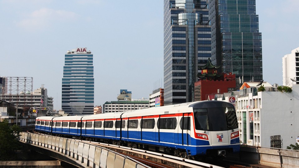
Bangkok Blue Line Extension Project, Contract 2 – Thailand

The MRT (Metropolitan Rapid Transit) Blue Line is being extended.The extension is expected to be completed in 2017 and by then the Blue Line will become a loop line around the centre of Bangkok, with the part on the western side of the Chao Praya River mainly being an elevated system and the other half […]
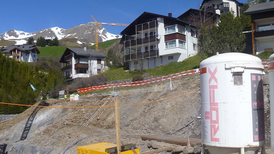
Arosa Schafisgade project – new touristic resort – Switzerland

The Arosa Schafisgade project includes construction of three houses with each six luxury apartments. The houses are located in a potential unstable slope. During excavation work adjacent houses above the new built ones had to be monitored geodetically. Between the new excavation and the existing houses borehole inclinometers had been drilled and monitored to detect […]
FAQ#116 – How do I configure a WR-Log digital node to read RS485 Sisgeo TIMED sensors?
Sisgeo digital instruments can operate in two powering modes: TIMED or ALWAYS-ON (for more information see F.A.Q.#094).A string of mixed instruments consisting of TIMED gauges and ALWAYS-ON gauges cannot work.The first thing to do is therefore to check that ALL connected instruments in your array are set to TIMED mode.You can check the powering mode […]
FAQ#094 – Which are the available powering modes for SISGEO digital sensors?
All SISGEO digital gauges can be settled in two different powering mode: The STANDARD powering mode is ALWAYS ON, so unless otherwise requested by the Customer, the sensors are settled as default in ALWAYS ON.
FAQ#076 – Why it is necessary add a termination resistor to the last digitized sensor of each RS-485 chain?
All SISGEO digitized instruments (IPIs, Tiltmeters, H-Level…) use the RS-485 serial communication protocol The RS485 protocol contemplate a termination resistor. The recommended chain connection is point-to-point (multidropped) nodes as a bus mode (line). Star, ring or multiply network connection are not recommended. SISGEO dataloggers has already a termination resistor assembled (typically 120Ω). On the opposite […]
FAQ#075 – What parameters are saved in SISGEO digital sensors? What information must the Customer provide when ordering?
All SISGEO digital sensors (e.g. IPI, BH Profile, MD Profile, LT Inclibus, Tilt-meter, RDS, H-Level, etc.) use the Modbus communication protocol over RS-485 serial. SISGEO digital sensors are connected to each other with a single signal cable. The parameters that are configured at the factory for each digital sensor are as follows: Upon confirmation of […]
FAQ#074 – Which kind of datalogger is necessary to read a SISGEO digital sensors?
The sensors are read connecting the end cable to a Modbus Master unit (i.e. OMNIAlog or miniOMNIAlog) with RS-485 interface (DCE, Half duplex, no Echo) able to manage communication with SISGEO Modbus RTU communication protocol. SISGEO’s communication protocol is available for the release upon request. The power [W] of power supply must be chosen according […]
FAQ#073 – Which is the maximum number of digitized sensors (RS-485, Modbus), the maximum number of chains and the maximum length of cable in a RS-485 network?
Last update: October 2021 All the SISGEO digitized sensors utilize a RS485 interface with Modbus protocol. 1.The maximum number of digitized sensors in a RS-485 network are 247 (theoretical) 2.The maximum number of digitized sensors chains that is possible to connect to Modbus master unit (as OMNIAlog or miniOMNIAlog) are 4. 3. About the maximum […]


