Sisgeo is proud to introduce an innovative inclinometer based on a 3-axis Micro Electro Mechanical (MEMS) accelerometer.
The selected MEMS has optimal thermal and long-term stability characteristics itself. Sisgeo tested it carefully to guarantee the final performances. However, the accelerometer itself is not capable to provide accelerations with enough accuracy and linearity to make inclination measurement, with sufficient performance.
For this reason, calibration is always necessary. Sisgeo has been calibrating single and biaxial sensors for a long time. Thanks to the experience acquired over time, Sisgeo is now introducing a brand-new calibration bench. The calibration bench is a custom designed machine that allows a precise reference angles generation, in the full -180/180° range, for all three axes. In addition, 16 tiltmeters can be calibrated in parallel.
Reference angles values are provided by an ultra-resolute optical encoder, with an accuracy of ±0.0001°. The accuracy of the whole bench is then periodically verified using certified references. During this process all the uncertainty of the metrological chains are also considered, to ensure a well-documented and reliable final error estimation.
Together with the calibration bench, a specific and custom calibration algorithm has also been developed. The algorithm involves several rotations and optimization calculations, covering all the 360° domain for all three axes. The calibration bench software automatizes the whole process, and it calculates parameters to compensate the cross-axis relations between axes and a set of optimal parameters capable of linearizing the accelerometer data.
Finally, the software automatically stores the calibration parameters into the inclinometer digital boards. The digital board is part of the instrument and is programmed to do all the calculations to correctly apply the calibration to MEMS’s raw values, in real time. The final data will then be accessible using standard Modbus protocol, over RS485, providing data in different digital channels. Everything is compatible with any Modbus master, including all Sisgeo’s datalogger family.
The accurate 360° calibration opens to a new and optimized warehouse and production flow: Sisgeo does not need to know if the sensor will be in horizontal/vertical or subvertical installation before the calibration (usually known only at order time). Any installation position will be compatible with the instrument.
The inclinometer can provide results in different perspectives. The user can then select digital channels to match whatever perspective is more suitable for its application, that may also change in time if the instrument is used in different installations.
- A first perspective is to provide three angles, one for every sensor’s plane: It represents the standard way to use the inclinometer and data can be retrieved from the channels 1, 2 and 3:
- Angle between accelerometer’s Z axis and gravity direction, in the plane identified by the Z and Y axes of the instrument. This angle is called αZY.
- Angle between accelerometer’s X axis and gravity direction, in the plane identified by the X and Z axes of the instrument. This angle is called αXZ.
- Angle between accelerometer’s Y axis and gravity direction, in the plane identified by the X and Y axes of the instrument. This angle is called αYX.
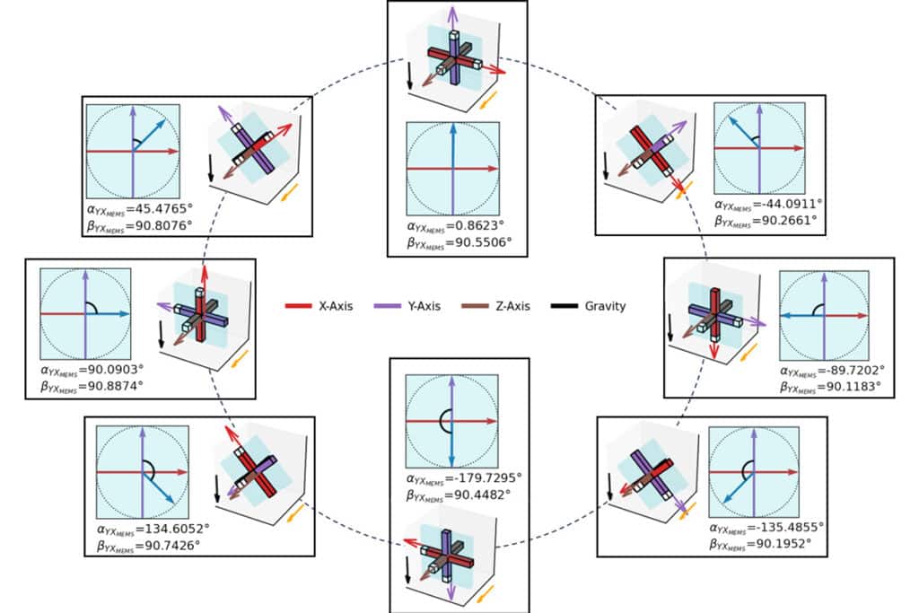
- The second one is an optimized two channels perspective, thought mainly for convergence application. In this perspective, to every α angle is linked a corresponding β angle, that represent how much the plane is tilted compared to gravity direction. An example of this perspective is shown in the figure below.
- Finally, three calibrated g values can be provided. They represent the core information. Sisgeo uses these values as input to get the above described perspectives. However, to get the information in angle units, users need to do their own calculations.
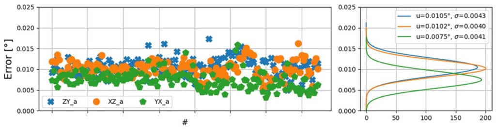
Thanks to the Sisgeo’s calibration bench, calibration algorithm and angle calculations, the performances are flat over all 360° range and compliant with the ISO 18674-3.
The maximum linearity error is defined as angle variation measured by the instrument minus the angle variation measured by the reference (in absolute value), plus all uncertainties in the measurement chain (including repeatability). The result is shown in the figure below where the distribution mean value (μ) and standard deviation (σ) are shown. The final error is below 0.02° over the entire 360° range.